Cable Connections to the Pi
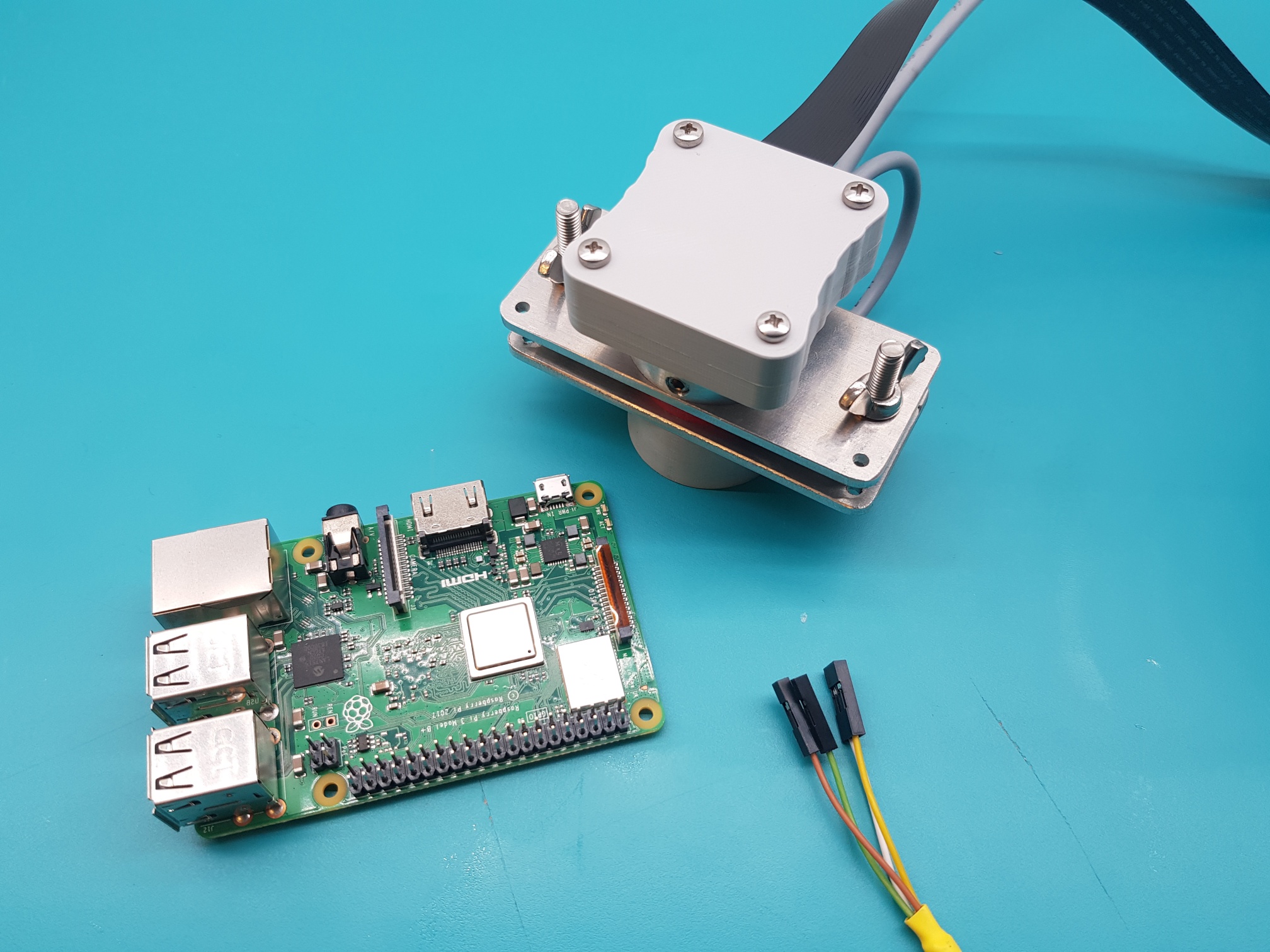
You will need
Cavicam with the camera installed
Raspberry Pi
Step 1
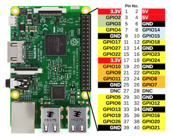
Using the reference diagram above…
If you have Green, Orange, White and Yellow cables: Orange = Pin 4, Green = Pin 6, Yellow and White = Pins 16 and 18 (order does not matter)
If you have Green, Orange and 2 Yellow cables: Orange = Pin 4, Green = Pin 6, Yellows = Pins 16 and 18 (order does not matter)
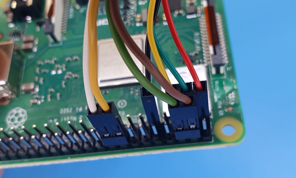
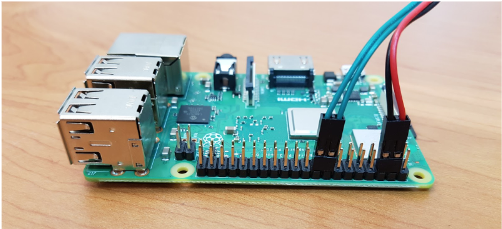
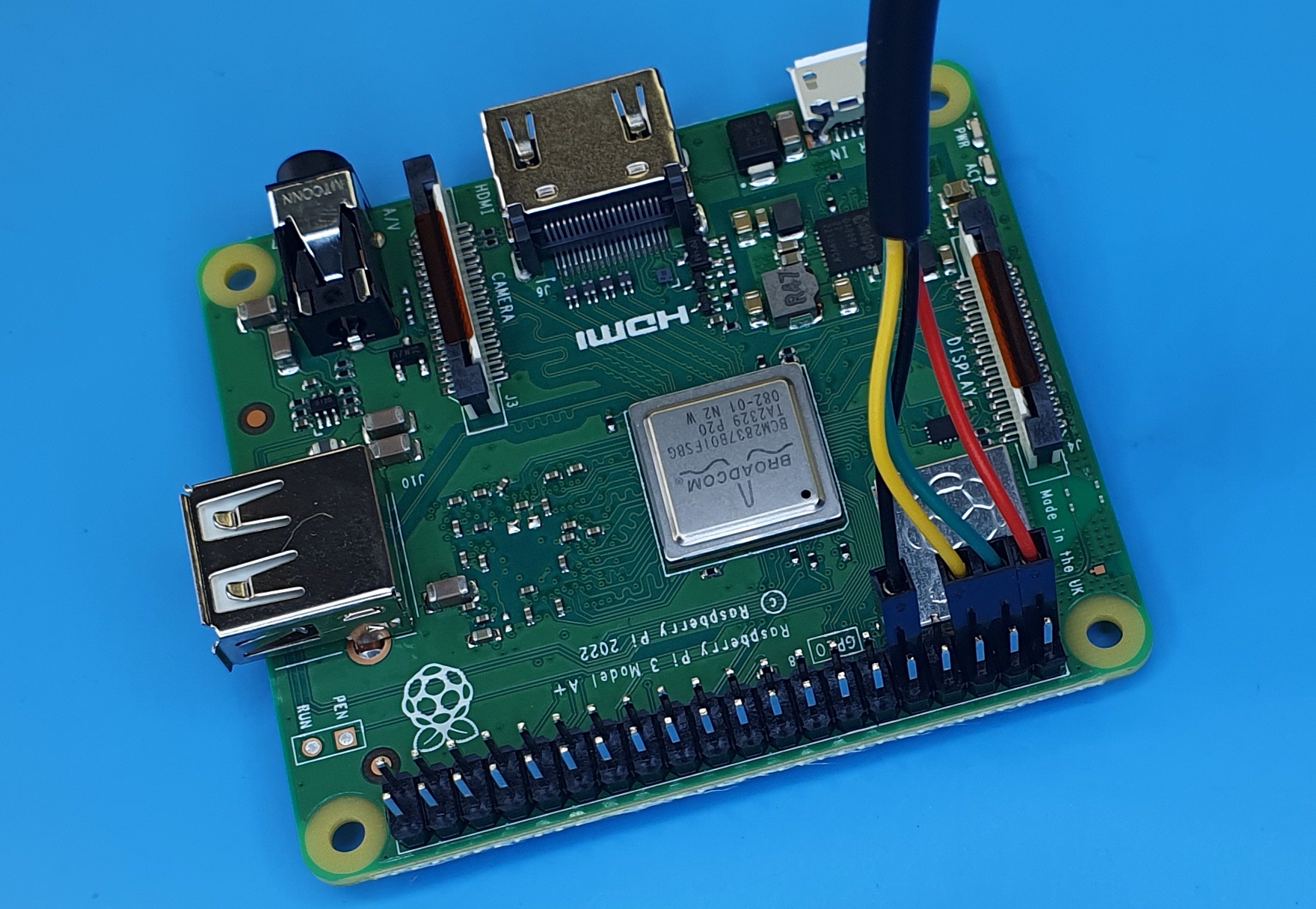
If you have Black, Red and 2 Green cables: Red = Pin 4, Black = Pin 6, Greens = Pins 16 and 18 (order does not matter)
If you have Brown, Green, White and Yellow cables: Brown = Pin 4, Green = Pin 6, Yellow/White = Pin 16/18
If you only have 3 cables (neopixel version): Orange = Pin 4, Green = Pin 6, Yellow = Pin 12
If using the Open Source version: Black = Pin 6 White = Pin 16 or 18
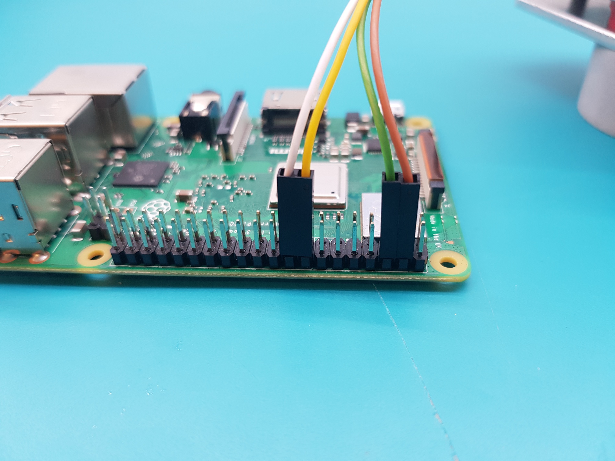
Example for green, orange, white and yellow cables
Example for black, red and 2 green cables
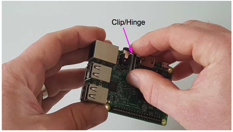
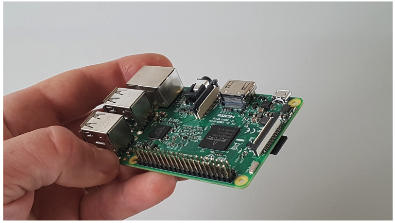
Step 2
Carefully unclip the clip/hinge on the camera cable connector on the Raspberry Pi.
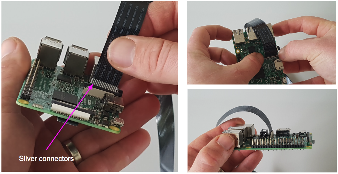
Step 3
Insert the camera cable (note the orientation of the silver connectors) and re-clip the clip/hinge back in position to lock the cable in position. When properly installed, the silver connectors should be barely visible, or not at all.
Temp Humidity Sensor
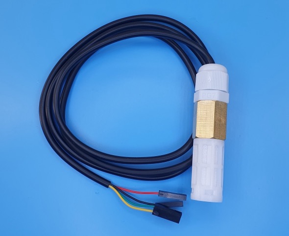
If you have a temperature and humidity sensor, connect:
Red cable to Pin 1 (3.3V)
Green cable to Pin 3 (GPIO2)
Yellow cable to Pin 5 (GPIO3)
Black cable to Pin 9 (GND)
Cable connections with cavicam and temperature and humidity sensor attached